


🚀 Unlock limitless control with the MCP23017 IO Expansion Board!
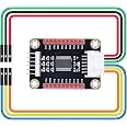
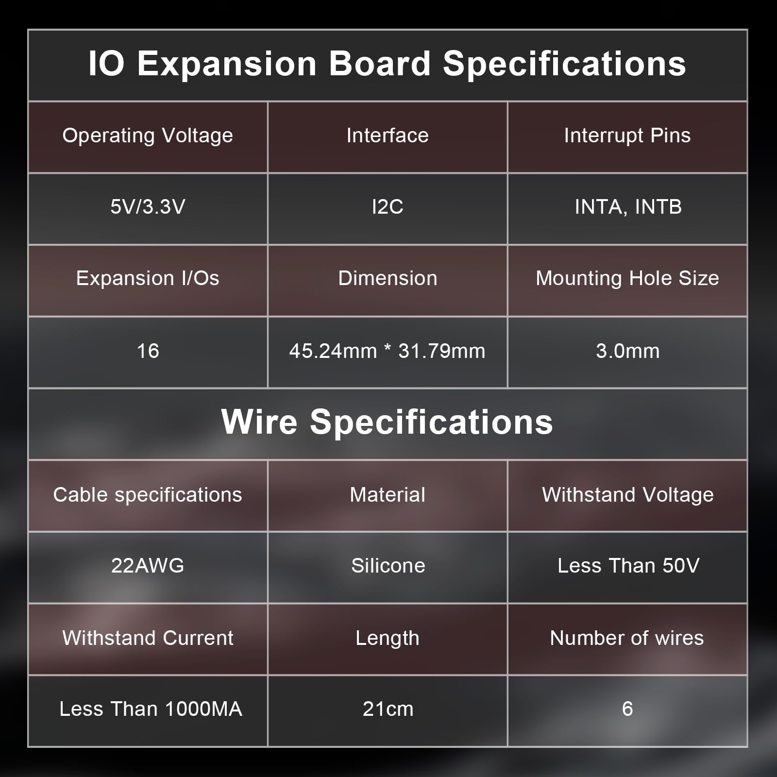
The MCP23017 IO Expansion Board dramatically boosts your microcontroller’s I/O capacity by converting 2 signal pins into 16 programmable input/output pins via I2C. Compatible with major platforms like Raspberry Pi, Arduino, Micro:bit, and STM32, it supports up to 8 boards simultaneously for a total of 128 I/O pins. Featuring configurable I2C addressing and durable, eco-friendly silicone wiring, this board is engineered for scalable, reliable, and sustainable hardware projects.
W**N
Amazing price, speed, tons of online documentation, and ease of use.
Amazing prices and ease of use. I have only tested in output mode, but I have never seen a product from Amazon that has so much online documentation and Arduino libraries. I am controlling 16 Solenoids with just a few lines of code. Extremely fast. You can daisy chain up to 8 of these modules to control a total of 128 pins using only two pins on your microcontroler. If your microcontroller supports 2 I2C ports, you can control up to 256 pins with single microcontroller.
J**E
Just as described
Purchased this to expand the number of GPIO pins in Pi. Works just as described.
E**S
Product is high quality, sample code could be better
Physical quality of the product is quite high. Comes in a plastic container. The container is barely large enough to contain the board and wires. But it does. There's no label on the top of the container which specifies what is inside. Would be nice it were nicely labeled rather than a generic CQRobot box.My testing setup inludes a Windows PC, Arduino Nano, breadboard, and some LEDs, resistors, and wires.No directions came with the product. Mostly expected. however the mentioned Wik says "Comes with development resources and manual." Which I guess means comes with the wiki? Kind-of cyclical, but whatever.The cqrobot.wiki page listed in the product description does contain some example code, but not everything that you need. The code requires MCP23017.h, which is not listed or available. I found some other code on the internet for the MCP23017 chip which helped me quite a bit. I ended up using that instead, and installing the Adafruit MCP23017 library in Arduino IDE.There's no details on the product description or wiki on exactly how to configure the address of the board. The cqrobot wiki sample code does show that it's default "7". Which is not the same as the default "0" from the other sample code I found. I didn't see any details on the cqrobot page explaining what R1, R2, R3, R4, R5, and R6 do. Nor what A0, A1, and A2 do. Using a multimeter I found that resistors 4-6 set address pins to vcc, which matches the address 7. I wish this was a bit better described what was going on here, and how to make the change. I'm guessing a 0 ohm resistor, or solder bridge, on A0-2 will set the address to 0. Would be nice since this is a breakout board if those were jumpers or switches to change the address.I did end up getting the board/chip to work! So that's good right.Product does work on 5 or 3.3v rails.
D**R
Great GPIO expander (see details). Recommened
The CQRobot Ocean: MCP23017 IO Expansion Board - I2C Interface, Expands 16 I/O Pins is a multiplexer, of sorts. I added the library in the Arduino IDE, and was able to access the MCP23017 on the default I2C address. I haven't had a need to change the address, yet. As for the board, it appears to work fine. Obviously, the expansion GPIOs are a little different to get to than the onboard GPIOs, but the difference isn't all that significant.I've really only run out of GPIOs on a couple projects - and my solution in each of those was to bey a more buffed-out microcontroller. At $9, this is a better, cheaper, and more scalable alternative. Recommended
Trustpilot
3 days ago
1 week ago