🔌 Charge Ahead with Innovation!
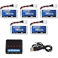
The 6PCS 2A USB 18650 Lithium Li-ion Battery Charger Module is a powerful and adjustable DC-DC step-up boost module designed for DIY enthusiasts. With a maximum discharge current of 2A and an input voltage range of 4.5-8V DC, this module allows for continuous output voltage adjustments from 4.3V to 27V, making it ideal for various applications including multimeter conversions and lithium battery charging.
| Output Voltage | 5 Volts |
| Input Voltage | 4.5 Volts (DC) |
| Item Weight | 1.13 Ounces |
| Color | 6 PCS |
B**Y
Works well with Solar panel and Li batteries
Well made unit. Easy to adjust. Just the type of board I was looking for
A**R
powering a 12V fan with my phone power bank
Works pretty well. Just watch out because twisting the dial just a little makes it jump high in voltage, so turn it little by little and don't power anything valuable until you have the voltage set right.I have a 12V fan and wanted to use a USB power bank since I can also use it to charge my phone, and generally they're cheap and readily available. This worked, and for $10 you get a pack of 6, so I can slap them onto several fans.
F**O
Horrible!
Only 1 out of 6 worked and the potentiometer on it, did not work at all. It turned on (green and red LED) and could not get the output voltage to drop. The output stayed at 27.8 volts no matter what. The input voltage was 5 volts using a phone charger. I'm very disappointed in this, and would give it ZERO stars if I could.
J**H
No Low Voltage Cutoff
So my first impressions of these little boards are positive.As long as you understand their limitations, you should be fine.The "2A" rating on the listing is ... generous. The boards start getting a little frisky warm outputting 5v1A, but nothing I was afraid of.Outputting 12v 350mA for about 4w, the boost chip got frighteningly hot. The board WAS running, but I discontinued the test for fear of damaging it, or more importantly, the device I was powering.It looks like you lose efficiency rapidly with higher amounts of boost. Monitor the temperature of the board closely when using higher boost voltages until you are sure that heat is manageable.Continued testing found that the board DOES NOT POWER DOWN when your cell's voltage runs low.The regulator loses regulation, emits an audible whine, and output voltage begins dropping.In my testing, the 12v 4w load had dropped to about 7v (still at 4w), and my cell had reached ONLY. TWO. VOLTS. (That is bad.)I very strongly recommend purchasing some "BMS/battery protection" boards to go along with these, or to use cells that are already equipped with protection.Fortunately, such protection boards are readily available here on Amazon and are very affordable.The on board charger is preconfigured for 1A. I haven't thrown a meter at it. They're going to vary give or take a few mA just due to the tolerance of the charge rate resistor.The charge indication lights are not very bright. I consider this good. No eye-searing brilliant blue lights here. Just a soft red light for charging, and similarly soft green light when fully charged.You can adjust the charging speed of the boards by replacing the "122" resistor near the edge of the charging side of the board. This will preserve the life of your cells, especially small ones, at the cost of requiring more patience from you during charging.Consider reducing charge current a little if you are using very large cells, for heat management and reliability. Some reviewers have had the charge systems on these boards blow out when trying to charge very large cells. This would protect you from that.Here's a table for replacement charge resistor values and what charge current they'll give you.When using small cells, find a value that closely matches but does not exceed the mAh rating of your cell.- I wouldn't use a converter this powerful on a cell below 250mAh. -5kO - 250mA4k - 300mA3k - 400mA2.2k - 500mA2k - 600mA1.6k - 700mA (good for 750mAh)1.5k - 780mA (close enough to 800mA)1.3k - 900mA1.2k (Stock) - 1ADo not go below 1.2k. You can overheat and blow out the charging chip.The output adjustment dial is very tiny and very sensitive. I'm highly experienced in adjusting touchy little potentiometers like this, but I could see others struggling. The first board I sampled had no problems going from about 4v to about 29v open circuit. They are only designed for boost mode operation though, so should be considered unreliable below 4.5v minimum.I had no problems with voltage stability. Output rises a small amount when the board is heavily loaded, as the converter appears to be equipped with a wire loss compensation feature.I've had no signs of positive voltage excursions - a problem I had with another boost/buck converter that ended up blowing up a beloved electronic device and ruining my day as a result.Output falls off dramatically when your cell is depleted, however this regime of operation is hazardous to your cell and should be avoided.Use a BMS/protection circuit. Please.
E**Y
I thought there was a design flaw but I was mistaken.
The switching supply is always energized with a Lipo battery in place which led me to believe the battery would drain even under no-load conditions. As it turns out, when no load is applied the switching supply draw is only 0.18mA when the output is adjusted just north of 5V. Changing my two star rating to 5. :-)
C**M
The ones that worked aren't bad
As the title says the ones that work are pretty good and handy. However out of 6 only 3 work. 1 doesn't even have the USB pins soldered to the board and gets super hot when plugged in. Another has a major short somewhere. At least it's cheap.
R**Y
OK , i guess. no not ok
bought the six pack ,one had a damage usb connection . Three were not able to adjust output voltage downto 5 volts .Probably will be alright for other applications .these chargers must be 2nds and 3rds. the 2 that i was able to lower the voltage on both died within a couple of days.I have used these before ordered from china, never have had these problems.these are junk.
C**.
Short-circuit on USB input - returned them
Took one of them out of the bag, connected a USB cable to it and the other end in my PC. The PC shutdown!That was scary. Measured the input side with a DMM and it had 1Ohm. Measured the other boards, across input they all had 1Ohm which is equivalent to a short-circuit across USB input. Removed the capacitor and 0 Ohm resistance and the short was still there. The only thing left was the USB micro connector. De-soldered that one == no short circuit anymore. It's a design problem, the plus side extends too much under the USB connector and shorts with the metallic part. After scraping a bit of the trace, soldered back the USB, a battery and everything works.
Trustpilot
1 month ago
2 days ago