We remain fully operational. Our teams are working around the clock to ensure your deliveries continue safely.

DOWNLOAD THE APP


Copyright © 2025 Desertcart Holdings Limited
DOWNLOAD THE APP


Buy anything from 5,000+ international stores. One checkout price. No surprise fees. Join 2M+ shoppers on Desertcart.
Desertcart purchases this item on your behalf and handles shipping, customs, and support to Vanuatu.
🚀 Elevate your IoT game with MakerFocus ESP32 OLED — where smart meets sleek!
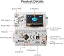
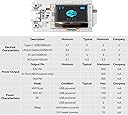
The MakerFocus ESP32 OLED WiFi Kit V3 is a compact, highly integrated IoT development board featuring a dual-core 240 MHz ESP32 processor, onboard 0.96-inch OLED display, and built-in WiFi (802.11 b/g/n) plus Bluetooth 5 connectivity. Designed for seamless Arduino IDE compatibility, it includes a lithium battery management system with Type-C power input, making it ideal for smart city, home automation, and IoT maker projects requiring reliable wireless performance and real-time data visualization.
| ASIN | B076KJZ5QM |
| Best Sellers Rank | #4,249 in Single Board Computers (Computers & Accessories) |
| Brand | MakerFocus |
| Built-In Media | 1 * ESP32 Development Board, 1 * Power Cord, 2 * Pin Headers |
| CPU Model | None |
| CPU Speed | 240 MHz |
| Compatible Devices | Arduino devices, IoT devices, microcontrollers |
| Connectivity Technology | USB, Wi-Fi |
| Customer Reviews | 4.2 out of 5 stars 320 Reviews |
| Item Dimensions L x W x H | 1.97"L x 1"W x 0.41"H |
| Item Weight | 4.54 g |
| Manufacturer | MakerFocus |
| Memory Storage Capacity | 8 MB |
| Mfr Part Number | UZM173505AEVXI378 |
| Model Name | WiFi Kit 32 (V3) |
| Model Number | 8541612336 |
| Operating System | Arduino IDE (compatible with Windows, macOS, Linux), FreeRTOS (firmware) |
| Processor Brand | Espressif |
| Processor Count | 2 |
| Processor Speed | 240 MHz |
| RAM Memory Installed | 8 MB |
| RAM Memory Technology | LPDDR |
| Ram Memory Installed Size | 8 MB |
| Total Usb Ports | 1 |
| UPC | 190033879688 |
| Wireless Compability | 802.11abg |
W**Y
this is a great little dev board, but there are serious documentation shortcomings
I am going to save you some time by repeating something another reviewer already stated "Use the pin labels on the bottom of the PCB". They noticed that the doc shows the device from the bottom. I also noticed the LEDs are on the opposite side in the picture. Maybe the picture was taken in selfie mode. I burned a day on this trying to figure out why my analog inputs were working but not the digital counterparts. I've ordered three of these in the last three months. They have all been the V3 board. The pin diagram (WIFI_Kit_32(New)) seems to have the correct analog pins labeled, but the GPIO pins are outright incorrect. I believe the problem is a bit deeper than just an inverted image. The GPIO pins still don't match inverted. I think their library is configured for the back silk screen labels, but the analog pins in the diagram I mentioned above are correct. so in short; use the diagram when using analog, and the back of the device when using digital. how fun!! otherwise these things are great for the price.
D**L
Arrived with bottom corner of OLED broken. - Update: Issue promptly handled by Seller
I give this 3 stars because when I unpacked it and set it up to test, I noticed that the bottom left corner of the OLED was broken off. I powered it on anyway to see if it worked. It partially worked ... the sample code was displaying text but it was missing lines. I assumed that I had handled it carelessly and wrote it off and ordered another. It arrived in one day (the other arrived in 2). When I removed it from the packaging (with much care this time), it ALSO had the bottom left corner broken off. It powered up OK but same sketchy display. While I like this format (OLED on WiFi board), I think it needs better shipping packaging, so two stars knocked off. I also ordered the LoRa version (x2) and they arrived undamaged and worked great. (All 4 devices were in an anti-static bag that was in a small yellow shipping envelope.The OLED doesn't have any support on the two bottom corners ... easy to get broken.) UPDATE: Seller has taken care of these broken devices and has indicated that the shipping packaging is changing, I REALLY like this ESP32 and OLED format so I have added back the 2 stars. Great customer focus and concern.
A**M
I like it! It does have a few nuances though.
This board is pretty cool. I bought it for the integrated OLED diplay. Very satisfied with it despite the minor issues. If you are just starting out, you may want to pass this one up for a more seasoned board like a Huzzah. But if you like hunting down information and learning the hard way, buy it. The issues I have with this board are minor to me but worth noting. The library needs more work. if you #include heltec.h, their library for the board, and nothing else in your script other than say a basic "Hello World" to the Serial and upload your script, it will crash the device and cause it to endlessly reset. Remove heltec.h and the script runs fine. I tried grabbing their latest from their github and it's none better. Most of their examples don't work. Luckily, pretty much any ESP32/ESP8266 stuff will work with it. There are some nuances: There are only 2 PWM GPIO pins. There is no analogWrite. You can use ledcWrite and a function to set the duty cycle and it works good that way. Just need to remember to call your function, instead of just using analogWrite. Though you could probably do a pseudo duty cycle with digitalWrite and delay. The built-in OLED uses three GPIO pins. SCL is GPIO15, SDA is GPIO4, and reset is GPIO16. This makes those pins unable to be used for most other things. The only display library I managed to get to work flawlessly with the OLED display was the U8glib by olikraus. Both U8g2 and U8x8 worked just fine for me. The lib is available on github. Note that I didn't try more than a handful graphic libraries. U8glib worked and I didn't need to continue searching for another after that. This still leaves you around 20 GPIOs to use and of that amount, 8 are input only. The pins are also only 3.3v tolerant and may be damaged if you connect to 5v. The original pin out diagram they released was wrong. The side with GPIO pin 36 is on the RST button side and GPIO pin 21 is on the PRG button side. They have corrected it and the correct version is available on their github site but I also attached it to this review. You can see they just blurred the board in their updated diagram. The annoying flicker of the BAT LED. If you do not plug in a battery to the battery connector, located under the board, the BAT LED will flash constantly. There is no way to programmatically shut it off that I know of. If you know a way, please I'd love to hear from you in the comments. All in all, this is a very good project board if you have a little bit of knowledge and don't mind poking around looking for information. ADDENDUM: I wanted to add one more thing, and this is stating the obvious, I had to solder the header pins on to the board. A couple of tips I can pass along is go ahead and unscrew the four screws that hold the OLED in place so you can move it and more importantly the ribbon cable out of the way a bit. This should give you plenty of room to solder the pins without the risk of touching the ribbon cable with the soldering iron. Then just screw the four screws back in but don't tighten too much. Just snug them up should be fine. You can stick the header pins into a breadboard to hold them in place while you solder a pin on each end. Should be good to go for the rest. Mind the heat though. For whatever reason my soldering iron melted part of one plastic pin holder on the header. It still works. This was my mistake, not a design flaw.
R**Y
Solid and Reliable
This is a great board. I've purchased three so far and have yet to experience a single issue. Yes, they are expensive, but so am I; My time is valuable, and I spend enough time tracking down software issues that I don't have any left for glitchy boards. ESP8266 boards you can go cheap on, some of the cheapest have also been some of my most reliable, but the ESP32 is a cranky diva on cheap boards. The extra 4MB on these is super nice, just make sure to specify the V2 board in your IDE.
[**]
NOT SUPPORTED
Simple. Follow the tutorial(s) FIRST and it will clearly illustrate this is NOT supported as the advertisement suggests. The Arduino IDE can be made to work, but the examples fail to compile. Lora is great, this is garbage. Buy something that is better supported than this joke.
C**S
Use latest Arduino IDE and you're golden
I was trying to make this work "the right way" via ESP tools. But really, just use the Arduino IDE, it's only a couple steps and it's so easy: 1) Download latest Arduino IDE 2) Visit github (dot) com / espressif / arduino-esp32 and follow the directions about adding the ESP32 via board manager. 3) Open Arduino IDE under menu Tools → Board there are now a ton of new boards at the bottom of the list. Choose the "Haltec WiFi kit 32" -- also Pick the right COM port. 4) To get library for display: Sketch → Include Library → manage Libraries... search for u8g2 and install it. Then put this in the sketch: #include <U8g2lib.h> #include <U8x8lib.h> U8G2_SSD1306_128X64_NONAME_F_SW_I2C u8g2(U8G2_R0, /* clock=*/ 15, /* data=*/ 4, /* reset=*/ 16); // ESP32 OLED WiFi Kit onboard LED #define LED_PIN 25 // ESP32 OLED WiFi Kit "PRG" button for input to programs #define PRG_BUTTON_PIN 0 void setup() { u8g2.begin(); u8g2.setFont(u8g2_font_6x12_mf); // fairly small font u8g2.setFontRefHeightExtendedText(); u8g2.setDrawColor(1); // normal, not inverted u8g2.setFontPosTop(); // x,y is at top of font u8g2.setFontDirection(0); // not rotated u8g2.drawStr(0, 0, "It Works!"); u8g2.sendBuffer(); } UPDATE: Still loving these! This is my new go-to MCU for development. The OLED makes debugging easy and at least there's the one "PRG" button you can watch in your sketch. I've bought more of these via a different listing and it is the same board. Oh, and don't press down REAL HARD on the face of the OLED, like trying to smash it down into another PCB ... if you do it hard enough, you can break the edge of the LCD and wreck the words showing up. :D So now I try to avoid pressing on the OLED itself. These boards are pretty tough. The soldering also isn't that hard - when near the ribbon cable for the display, hold the iron to the outside of the pin and board. Additionally, the PWM on pins 25 and 26 are super easy to set up. // pwm #define SIG_OUT 26 double freq = 15.8; const int pwmChannel = 0; // This is not the output pin, that gets attached later! const int resolution = 10; // Resolution 8, 10, 12, 15 -> higher freq = less resolution pinMode(SIG_OUT,OUTPUT); // configure LED PWM functionalitites ledcSetup(pwmChannel, freq, resolution); // attach the channel to the GPIO2 to be controlled ledcAttachPin(SIG_OUT, pwmChannel); // set duty cycle based on 2^10 ledcWrite(pwmChannel,64);
M**X
Poor Docs. Good product.
Attached is the actual pin out. Be sure you are looking at V3 documentation. From the Heltec site I found installation instructions for the Arduino IDE (v2) that actually worked. the proper board selection is WiFi Kit 32 (V3) under heltec. Do simple I/O to verify before you add in the more complex libs. As for the battery, look at the schematic. don't be me and expect it to drop to 0 when you disconnect the battery while the USB is connected. (DOOH!) It is charging... I am using HT_SSD1306Wire.h-Miles Burton for the display and it is working well with functions like the Adafruit lib. The HelTec Example Factory_Test is the wifi scan that was pre-burnt on my board. Read the other comments here they also have good info. My main addition is the V3 pinout.
G**B
Use the correct cable for best results
This is a great product. I have used earlier versions with success on other projects. Using the USB-C connection is different - I could only get the V3 to connect with a USB-A to USB-C cable. A on the PC side and C on the board side. The vendor has not yet put information about these connections on the website, so it requires some trial and error.
Trustpilot
2 weeks ago
3 weeks ago