Deliver to Vanuatu
IFor best experience Get the App
🚀 Elevate your IoT game with MakerFocus ESP32 OLED – where smart meets sleek!
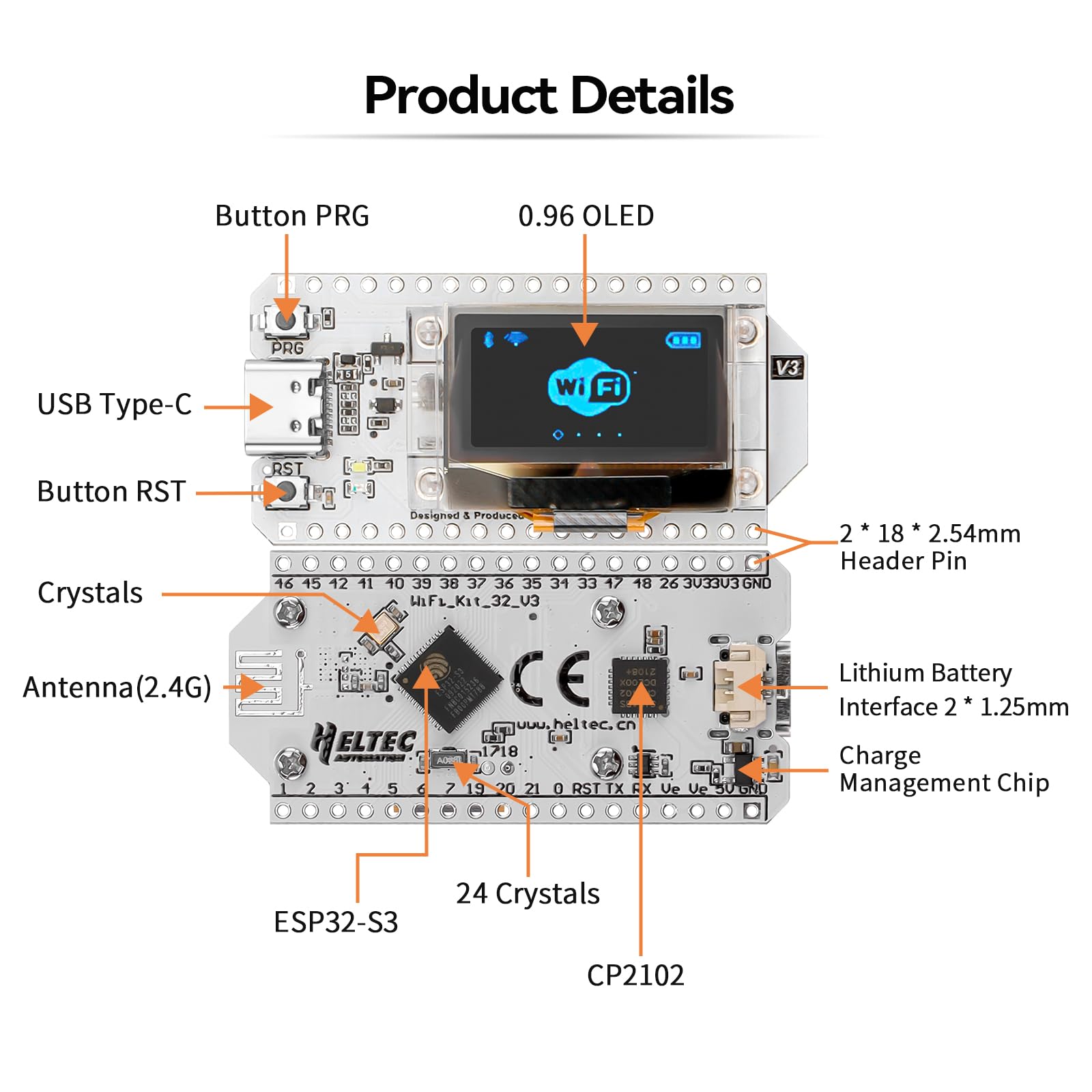
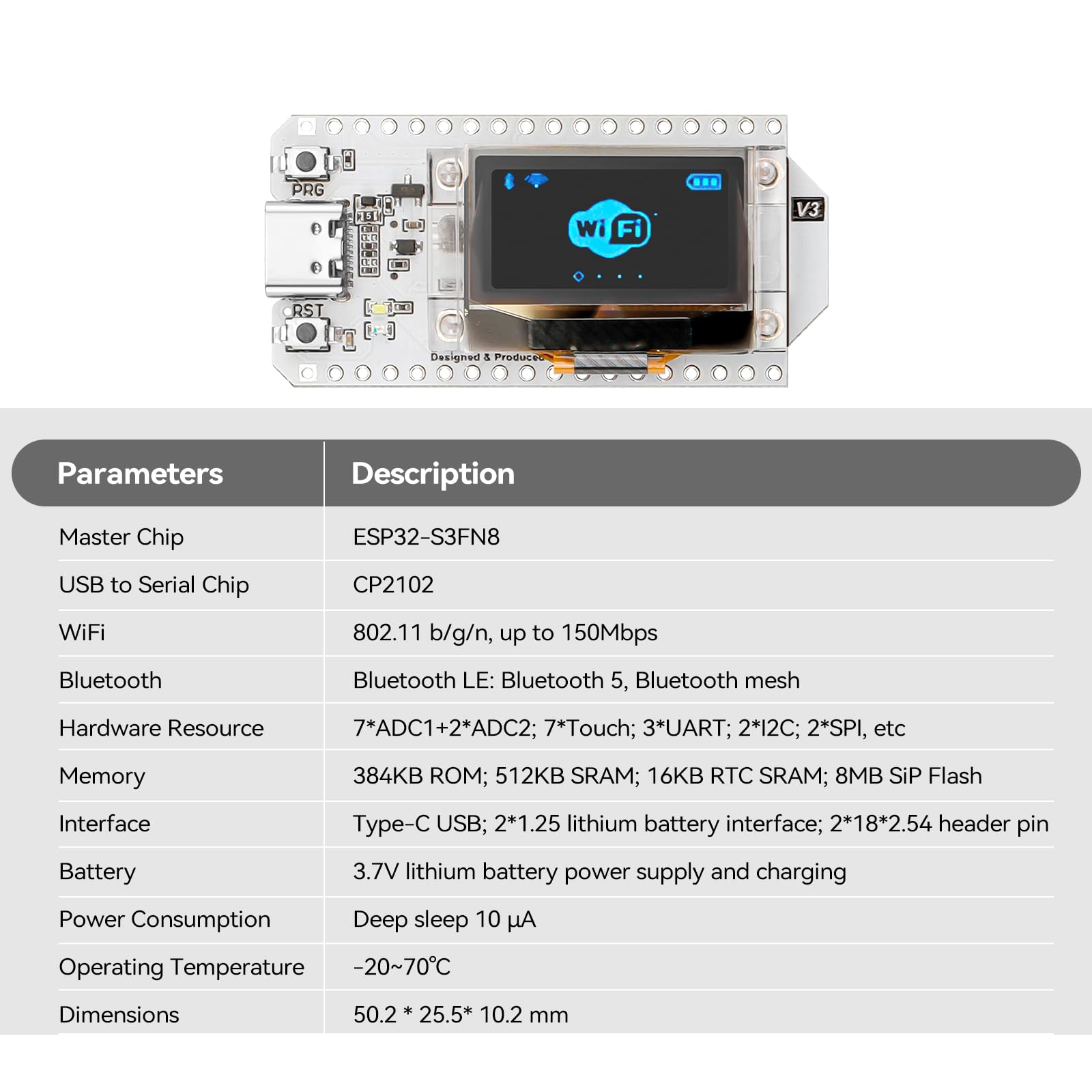
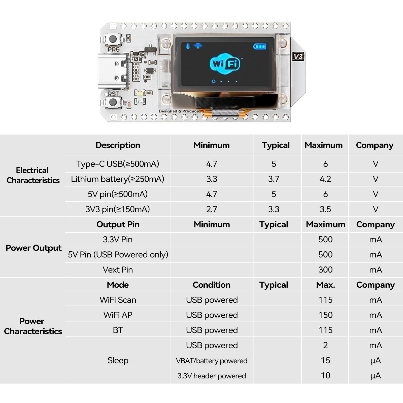
The MakerFocus ESP32 OLED WiFi Kit V3 is a compact, high-performance development board featuring a 240 MHz dual-core processor, integrated WiFi and Bluetooth 2.4GHz connectivity, and a crisp 0.96-inch OLED display. Designed for Arduino enthusiasts and IoT innovators, it offers versatile power options with built-in battery management and robust protection, making it ideal for smart city, home automation, and intelligent scene projects.
Processor | 240 MHz none |
RAM | LPDDR |
Memory Speed | 240 MHz |
Wireless Type | 802.11abg |
Brand | MakerFocus |
Series | WiFi Kit 32 (V3) |
Item model number | 8541612336 |
Item Weight | 0.16 ounces |
Product Dimensions | 1.97 x 1 x 0.05 inches |
Item Dimensions LxWxH | 1.97 x 1 x 0.05 inches |
Processor Brand | Espressif |
Number of Processors | 2 |
Voltage | 3.3 Volts |
Manufacturer | MakerFocus |
ASIN | B076KJZ5QM |
Country of Origin | China |
Is Discontinued By Manufacturer | No |
Date First Available | October 19, 2017 |
W**Y
this is a great little dev board, but there are serious documentation shortcomings
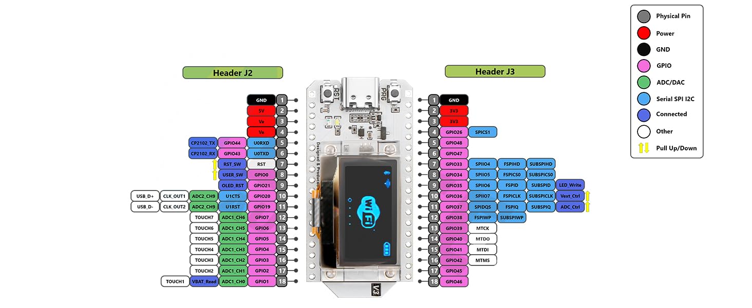
I am going to save you some time by repeating something another reviewer already stated "Use the pin labels on the bottom of the PCB". They noticed that the doc shows the device from the bottom. I also noticed the LEDs are on the opposite side in the picture. Maybe the picture was taken in selfie mode. I burned a day on this trying to figure out why my analog inputs were working but not the digital counterparts. I've ordered three of these in the last three months. They have all been the V3 board. The pin diagram (WIFI_Kit_32(New)) seems to have the correct analog pins labeled, but the GPIO pins are outright incorrect. I believe the problem is a bit deeper than just an inverted image. The GPIO pins still don't match inverted. I think their library is configured for the back silk screen labels, but the analog pins in the diagram I mentioned above are correct. so in short; use the diagram when using analog, and the back of the device when using digital. how fun!! otherwise these things are great for the price.
R**Y
Solid and Reliable
This is a great board. I've purchased three so far and have yet to experience a single issue. Yes, they are expensive, but so am I; My time is valuable, and I spend enough time tracking down software issues that I don't have any left for glitchy boards. ESP8266 boards you can go cheap on, some of the cheapest have also been some of my most reliable, but the ESP32 is a cranky diva on cheap boards. The extra 4MB on these is super nice, just make sure to specify the V2 board in your IDE.
A**M
I like it! It does have a few nuances though.
This board is pretty cool. I bought it for the integrated OLED diplay. Very satisfied with it despite the minor issues. If you are just starting out, you may want to pass this one up for a more seasoned board like a Huzzah. But if you like hunting down information and learning the hard way, buy it.The issues I have with this board are minor to me but worth noting. The library needs more work. if you #include heltec.h, their library for the board, and nothing else in your script other than say a basic "Hello World" to the Serial and upload your script, it will crash the device and cause it to endlessly reset. Remove heltec.h and the script runs fine. I tried grabbing their latest from their github and it's none better. Most of their examples don't work. Luckily, pretty much any ESP32/ESP8266 stuff will work with it.There are some nuances:There are only 2 PWM GPIO pins.There is no analogWrite. You can use ledcWrite and a function to set the duty cycle and it works good that way. Just need to remember to call your function, instead of just using analogWrite. Though you could probably do a pseudo duty cycle with digitalWrite and delay.The built-in OLED uses three GPIO pins. SCL is GPIO15, SDA is GPIO4, and reset is GPIO16. This makes those pins unable to be used for most other things.The only display library I managed to get to work flawlessly with the OLED display was the U8glib by olikraus. Both U8g2 and U8x8 worked just fine for me. The lib is available on github. Note that I didn't try more than a handful graphic libraries. U8glib worked and I didn't need to continue searching for another after that.This still leaves you around 20 GPIOs to use and of that amount, 8 are input only. The pins are also only 3.3v tolerant and may be damaged if you connect to 5v.The original pin out diagram they released was wrong. The side with GPIO pin 36 is on the RST button side and GPIO pin 21 is on the PRG button side. They have corrected it and the correct version is available on their github site but I also attached it to this review. You can see they just blurred the board in their updated diagram.The annoying flicker of the BAT LED. If you do not plug in a battery to the battery connector, located under the board, the BAT LED will flash constantly. There is no way to programmatically shut it off that I know of. If you know a way, please I'd love to hear from you in the comments.All in all, this is a very good project board if you have a little bit of knowledge and don't mind poking around looking for information.ADDENDUM: I wanted to add one more thing, and this is stating the obvious, I had to solder the header pins on to the board. A couple of tips I can pass along is go ahead and unscrew the four screws that hold the OLED in place so you can move it and more importantly the ribbon cable out of the way a bit. This should give you plenty of room to solder the pins without the risk of touching the ribbon cable with the soldering iron. Then just screw the four screws back in but don't tighten too much. Just snug them up should be fine. You can stick the header pins into a breadboard to hold them in place while you solder a pin on each end. Should be good to go for the rest. Mind the heat though. For whatever reason my soldering iron melted part of one plastic pin holder on the header. It still works. This was my mistake, not a design flaw.
J**G
Sorry Arduino... ESP32 is in!
I have been developing with Arduino for many years. It WAS my go to board. After learning of ESP32 I ordered this board after seeing it in a YouTube video. It is cheaper, faster, has way more options than any Arduino or variant I have ever used.. My Arduino's are now stored away and ESP32 will be my new go to. Large community. If you already use to Arduino IDE then this isn't any different. Within minutes have a WS2812B light strip running with a web server back end!
[**]
NOT SUPPORTED
Simple. Follow the tutorial(s) FIRST and it will clearly illustrate this is NOT supported as the advertisement suggests. The Arduino IDE can be made to work, but the examples fail to compile. Lora is great, this is garbage. Buy something that is better supported than this joke.
J**S
Not the device that is pictured
The device that was shipped is not what is in the pictures. I returned one for that reason and the replacement was the same as the one I returned. The device in the pictures has a USB-C (vs a micro USB on the shipped unit) and says V3 to the right of the OLED display. In researching a little further the pinout diagram for the V3 version is significantly different from the device that was shipped. If you have any plans of using it in a design that will be repeated in the future, the V3 version could not be substituted without significant re-engineering. (From the heltec website it looks like the V3 version is the new unit for the future. )From the other reviews, it sounds like a very capable device and the one that was shipped seems to be an upgrade from an original version, but from the original to the one that I received there were some changes in the pinout, mostly in the power pins, and to the V3 version the changes were extensive.
Trustpilot
1 day ago
1 week ago