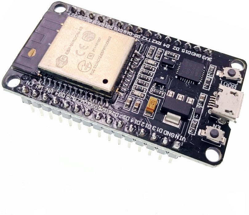


JZK ESP-32S ESP32 Development Board 2.4GHz WiFi + Bluetooth Dual Mode Antenna Module with Ultra Low Power
Product ID: 121776328
N**M
Great little board!
I installed MicroPython on this, and it works great. Chip is faster than the ESP8266 I was using. WIFI works. I haven't tested Bluetooth.I have no "real" use for any of the microcontrollers I've purchased over the last few years, but they have been fun to play with.
M**O
The Internet of Dings
The good, the bad and the ugly.First the good.This is a very low-cost but very powerful development board. It has two main processor cores capable of running ARM instructions at typically one instruction per cycle so it can really perform despite the modest clock speeds. It has WiFi, Bluetooth, Bluetooth Low Energy, magnetic sensor on board, analog ports, capacitive touch sensors and a ultra-low power co-processor which can, in theory, run for months on a single coin cell. (The main processor goes into deep sleep while it does this and is only woken by the co-processor when needed so this is a great way to save power in portable devices.) It’s cheap too – very cheap for what you’re getting.There are a lot of projects out there for the Raspberry Pi using electronics but the vast majority don’t need something as powerful as the Pi – not even the Pi Zero. This board is the complete opposite. While it’s not massively powerful (although it outperforms, say, the computers that put men on the moon) it has loads of sensors, it’s far cheaper and often far more practical too.Now the bad.The instructions: there aren’t any. I mean not a jot. The best we get from this device is a reference to a Github page that hasn’t been touched in over two years and probably longer. This is for the manufacturer’s uRTOS (micro real-time operating system) and the Lua programming language. But using that means building your own toolchain and, I assume the rest of the stuff, from scratch and most of us don’t have time for that. We just want to stick it into a breadboard and play, right?Thankfully, the Internet and Limor “Lady Ada” Freid come to the rescue in the form of loads of tutorials and pre-made libraries so, with a little bit of searching you can find out that it is indeed possible to plug this into an Arduino IDE and get cracking.And the UglyAnd this folks, is where it gets really, really ugly. There’s a TL;DR at the end if you’re inclined.I’ve now got two of these (which might leave you wondering how after the tone of this review) but allow me to explain. There are a lot (and I mean A LOT) of clone boards out there based on this chipset and not all of them are created equal. Some are very good, some … not so much so and this is one of them.When the first one arrived (with a little ding in the shield) I was worried that it had gotten damaged in the post but gave it a go anyway. Nada. Not an electronic sausage. It powered up – the red LED glows but the computer didn’t see the UART tethered to the USB connection. Things were not looking good.So, with minutes to spare (and a deadline to meet) I ordered another and Amazon delivered (brilliantly) as ever.In goes the new one and … ooops. Another faulty one? Can’t be. After some searching and two more micro-USB leads later I find myself able to communicate with the UART, so maybe the first one isn’t jiggered after all.Sure enough, the UART responds and I feel a bit foolish for not checking the wires in the first place. So it’s all my fault and off I go to program my first Arduino sketch. It should be said that there is a system to include these development boards into the Arduino IDE but that’s really something better explained by people who have made videos about it.Once you’re set to go, you hit the upload button and wait.Like magic, the little board fired into life and stuttered a bunch of integral signs all over the serial monitor. As dumb as I am, I figured that couldn’t be right. The blue LED (used in some sketches for testing, stubbornly sat there… dull, uninterested and unlit.)So I popped the “dead” board in to see what would happened and … nothing. Although Linux (I’d moved from Windows because I prefer the ease of Linux for hardware development) and held my breath and …Things went from bad to “oh, so it was dead all along”.No amount of begging, pleading or generally swearing in the direction of this little beastie was going to get the sketch to upload. Noooooo!“Right… it’s going back to Amazon!” I figured and filling in a tart response to why I was sending it back.Meanwhile, the other board also developed an eerily similar fault. Sometimes sketches would upload, other times the same one would stall, falter and on occasion not even transfer at all.Perchance in my fury I happened across Mr. D. Lambert’s review where he mentioned that it was necessary to hold the “boot” button – it’s a tiny switch as one might expect – until the sketch starts to upload.You have to do WHAT?!But sure enough, holding down boot the serial console sparked into life and a whole load of technical details spat down the link – in English no less – giving all manner of detail about the board, WiFi and so on.That wasn’t expected, but again, the other board behaved slightly differently – but I did notice that even the working board experience a very slight delay before the sketch started to upload – unless I held boot.That just didn’t make sense but while I was looking for tutorials and examples (I’m selectively lazy, it’s a good trait in programmers) I chanced upon a site detailing soldering (!) a 100mfd capacitor close to the processor case and down to the EN pin. We’re talking some delicate soldering there that’s well outside the scope that most makers would want to attempt – even me and I used to be very good at it.These days 100mfd capacitors are cheap and fairly small but getting one at 1am when even Amazon has stopped taking orders… well. Out comes the radio spares box after some rummaging, I found some very old (recovered) 10mfd caps wasting away in the corner of a draw!Eureka! Out with the soldering iron.But another look at the board and it’s a hard no: soldering with a 25+ year old Antex CX18 and a tip that’s probably being used to melt plastic… and no sponge. Maybe not.Somewhat bizarrely, the choice of where to solder this capacitor turns out to be less important than how it acts electronically and to cut this “War and Peace: ESP32” story a little shorter, all you actually have to do is tie EN pin (top right of the board, next to the WiFi antenna) to GND which is the last but one pin on the right-hand side. The chance of making a mistake on such large pins (making a solder bridge for example) is far reduced and, frankly, it just looks better because you can’t see it.Much to my surprise – even on the breadboard – the “dud” sprang into life without any delay and without having to hold the “boot” switch down. It worked first time and every time – even uploading faster than the working one. Clearly, both of these boards (most of these clones if the Internet is to be believed) suffer from exactly this fault. Some are just worse than others.But electrolytics are a chunky (even the newer ones) and tantalum beads which in my day were the smallest we could get, are still polarised. While this isn’t a big issue, it just takes a little care in identifying the correct orientation, my mind was wondering what purpose this serves.A few capacitors from the spares box later and I’d discovered to my surprise that the actual value is not that important. I finally settled on a 15nf ceramic – which are longer lived than electrolytics ( the ones most likely to fail even in modern electronics). This wasn’t a design decision it was – that one has sufficiently long leads to make the jump!And it works. From 100mfd to a tiny fraction of that? My very quick and unscientific tests (so bad my old instructors would disown me) suggested that the smaller capacitors are more reliable. Not that it matters, we shouldn’t have to do this in the first place but I’m leaving my experiences here so that others aren’t caught out the same way.TL;DRYou’re going to need to solder (or breadboard) a capacitor between the EN and GND pins if you want this thing to work as its supposed to. It’s a dreadful design mistake and I’m grateful to the guy who discovered it but this should never have happened.It cost me an extra board to find this out, but now that you know, you won’t get caught out!As a quick aside, if you want to light the blue LED, it's #2 in the Arduino examples from Adafruit.
M**T
Good little unit once one understands a couple of things
The media could not be loaded. Criticisms:To use breadboards with this board one has to have two and straddle both of them with the ESP32. The reason is that the board is too wide to fit on just one breadboard and give access to all the pins. The second thing to note is the pitch between the pins mean that it is a struggle to fit it into one breadboard. You'll see from the photo I've included that when one straddles two breadboards, they have to be slightly apart because the pitch distance between the pins is non-standard.The second thing to note is (thanks for those that told me) one has to hold the BOOT button down to enable uploading to the ESP32, and once uploading commenced I could let go of the button. (Wait until you see Connecting in the Arduino IDE, press and hold the button, then release once the upload starts).That's the gripes over with. Aside from the pitch being non-standard and programming requiring holding the BOOT button, it's great!I put a short bit of code together for you to try. It drives a common anode three colour led. Simple but fun. I hope this is readable in the review, there isn't a "code" facility to preserve the formatting.#define ledR 27#define ledG 12#define ledB 13bool up; // determines direction of count up or downint n; // the counter used to know which leds to lightvoid setup() { // set the esp32 pins used for the led as outputs pinMode(ledR, OUTPUT); pinMode(ledG, OUTPUT); pinMode(ledB, OUTPUT); n = 1; // initialise to a valid value up = false; // set to false because it will be inverted when entering the loop // and we start from n = 1 so want it to count up // using a common anode tri-state led, so pulling down for on // start with all high (off) digitalWrite(ledR, HIGH); digitalWrite(ledG, HIGH); digitalWrite(ledB, HIGH);}void loop() { do { lightLed(n); // call the led switching function if (n == 1 || n == 7) // when the min (1) or max (7) is reached... up = !up; // toggle the count direction (up)?++n:--n; // the quick way to write the code commented out below, read // 'The C Programming Language' by Kernighan & Ritchie // (who created the C language) if you don't know how to do this /* if (up) // if counting up... ++n; // increment n else // otherwise --n; // decrement n */ } while (true);}void lightLed(int value) { // each LED is represented by one of the bits of the value n // bit 0 = red, bit 1 = green, bit 2 = blue // value contains a value between and including 1 and 7 // the result of (value & bit(x)) is converted to a bool and then inverted by ! // which we do because we are using a common anode led and pulling pins down to // turn the leds on digitalWrite(ledR, !(bool)(value & bit(0))); digitalWrite(ledG, !(bool)(value & bit(1))); digitalWrite(ledB, !(bool)(value & bit(2))); delay(500); // time to admire the different colours}// __// _ESP32_ [LED ]// | | [____]// | |-- D13 ---[220 ohm]---------------------------------------'|||// | |-- D12 ---[220 ohm]----------------------------------------'||// | | +ve 3.3v on esp32 ---longest leg of led-----'|// | |-- D27 ---[220 ohm]------------------------------------------'//
A**R
Pretty Poor
It works, but getting there is inordinately difficult for such a simple standard device.The referenced installation is flawed, fails to download, compile both for Windows and Linux. Abandoned.Diverted to micropython, and independently downloaded and installed.The units repeated showed signs of no response to esptools and rshell, yet a successful upload and burn seemed successful via USB. Instigating 'Boot' overcame, but subsequently won't communicate, despite 'EN'.Many have stumbled across this.This particular board requires a 10 uFarad electrolytic capacity between the EN and GND Pins. Discovered after 48 hours of head banging.Better quality boards do not require this.Fine if you are aware.
P**L
Fast easy to use, has WiFi, BT, USB and Over The Air updates.
Below are tips for those new to the ESP32 to help you get going quickly with this superb little board.Please use a good quality usb cable it does make a difference to the 5v rail when usb powered.EN=reset, Boot is used to reliably upload your sketch, press and hold as soon as the IDE says Connecting....., only let go when you see upload activity.Be aware some pins are not available when using wifi, there are several board versions 30 or 36 pin differing slightly.Do not connect GPIO pins directly to Gnd use a 100 ohm resistor.Check out random nerd tutorials for further tips. Have fun regards Paul
F**T
Absolute bargain
Disclaimer - I received a full refund after reporting a minor fault, making my unit effectively free.This is probably the lowest one-off price you'll pay for an ESP32.EPS32s a great. Highly recommended. It's a fully functional and easy to use Bluetooth/WiFi module with a micro-controller built in; or a micro-controller with a WiFi module built in - whatever way you want to look at it. Forget Arduinos and shields, this is everything in a tiny package.The hardware is open source (credit: Wei Wang/doit.am), so there are many variations to choose from. This PCB version is 0.1" wider than some ESP32 modules (see photo), which leaves rooms for mounting holes but with molex pins attached it's a row too wide for a standard prototyping board.Mine arrived with a fault in the molex pins, which were soldered on at a funny angle. I got a full refund without even asking for one so I can't fault the customer service. I'm assuming mine just slipped through quality control, but as I will probably remove the pins anyway (a complete pain to do) so I can attach wires to the PTH I could have lived with it. So in spite of the slight flaw, the customer service has restored it to five star.The extra width allows the edge pins to be silk-screened with labels, which is useful. Many of the pins are GPIO, and I believe there are three ACIAs (UARTS) built in; one of which is used by the USB via a converter chip.The whole thing runs beautifully cool.For software, the Arduino IDE "just works" with it, once you've installed the board package. And this includes complex libraries allowing you WiFi, DNS and IP socket drivers - including encryption on the WiFi and SSL. I absolutely love these boards.The picture is this board (right) next to a different, narrower, ESP32 board on the left. Both use the same ESP32 model at the centre. It shows the prototyping board problem, which is easy enough to overcome with a different prototyping board (or two of them).
Trustpilot
2 weeks ago
2 months ago