We remain fully operational. Our teams are working around the clock to ensure your deliveries continue safely.

DOWNLOAD THE APP


Copyright © 2025 Desertcart Holdings Limited
DOWNLOAD THE APP


Buy anything from 5,000+ international stores. One checkout price. No surprise fees. Join 2M+ shoppers on Desertcart.
Desertcart purchases this item on your behalf and handles shipping, customs, and support to Vanuatu.
🔌 Power Up Your Projects with Precision!
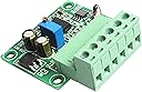
The NOYITO Frequency to Voltage Converter Module is designed to convert frequency pulse signals ranging from 0Hz to 10KHz into analog voltage signals of 0-10V or 0-5V. Ideal for applications involving PLCs and inverters, this module supports direct input of 5V, 12V, or 24V signals without the need for additional resistors. With a compact size and a wide power supply range of DC 12-30V, it’s the perfect solution for motion control and automation projects.
| Output Voltage | 10 Volts (DC) |
| Item Dimensions | 1.97 x 1.77 x 0.39 inches |
| Item Weight | 20 Grams |
| Color | Green |
D**L
Beware of high voltage output
This is a decent module that performs well. In my limited testing, it showed a fairly linear correlation between frequency input and voltage output. However, there is one thing you need to be aware of. The units which claim to have a 0-5V output will continue to increase output voltage if you increase the input frequency beyond the end of the range. For example, I have the 0-1KHz, 0-5V module. If I apply 1.15KHz to the input, I get 5.75 volts output. I was able to get output voltages over 10 volts with high-enough input frequencies. If you are attaching the output of this device to a microprocessor A/D input, you need to provide proper input protection. These modules may actually all be the same, with calibration being the only difference.
J**M
No wiring instruction or any paperwork for that matter.
Not one diagram or any paperwork to wire up.
A**R
What am I buying?
OK, so this module is based on classic LM331 IC configured in F-V mode. You can find complete schematic in LM331 datasheet with minor changes in actual implementation. Manufacturer was determined to hide all IC markings in PCB design, so all IC's have been sanded to remove original printed identifications.PCB implementation is old with very poor layout planning. Layout recommendations from IC manufacturer are basically ignored; with various components randomly placed on board, with trace routing basically wild and without consideration for cross-talk or intelligent management of layout. Many traces run under or around other components to destinations; when a little pre-layout planning could have made implementation much more efficient with improved performance. The use of obsolete DIP style LM331 IC is very interesting, especially when other components in design are surface mount. Guessing designer got great deal on very old date coded IC's.The only addition to circuits (not directly from datasheet application circuit) is an operational amplifier buffering output, configured as non-inverting (SOIC-8 package IC on PCB). Op-amp used as output buffer with discrete zener-diode based bias on negative input resistor. And voltage regulator LM78M12; which is medium power 12VDC regulator for entire board.Interface connector is severely oversized for use (pins most likely rated for 10A or more). Again, designer got great deal on obsolete new-old stock. PCB implementation could have been much more compact using components better suited for circuit and use. Obviously designed from NOS components for lowest cost and convenience.FYI, circuit can be modified in any way suitable for LM331 implementation. This implies PCB components can be modified to alter circuit functionality and performance (contrary to what manufacturer states).
I**N
are you trying to fry my encoder???
12 V across the encoder input pins. what
Trustpilot
2 weeks ago
2 weeks ago